TM-9-2320-272-23-2 - Page 1227 of 1417
REMOVAL
1.
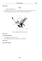
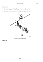
Remove two locknuts (Figure 1, Item 1) and mounting screws (Figure 1, Item 3) from angle bracket
(Figure
1, Item
2) and instrument panel (Figure 1, Item 6). Discard locknuts.
2.
Lower floodlight control switch (Figure 1, Item 4).
NOTE
Tag connectors for installation.
3.
Disconnect four connectors (Figure 1, Item 5) from floodlight control switch (Figure 1, Item 4).
6
M8021DAA
1
5
4
3
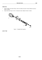
Figure 1.
Floodlight Switch Installation Removal.
END OF TASK
TM 9-2320-272-23-2
0320
0320-2
Back to Top

