TM-9-2320-272-23-2 - Page 1277 of 1417
REMOVAL (M931/A1/A2)
NOTE
Left and right composite lights, covers, and brackets are replaced the same way.
1.
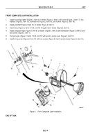
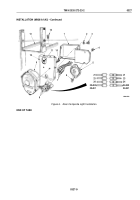
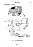
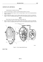
Remove two locknuts (Figure 9, Item 6), screws (Figure 9, Item 12), and reflector (Figure 9, Item 11) from
bracket (Figure 9, Item 5). Discard locknuts.
2.
Remove four locknuts (Figure 9, Item 9), screws (Figure 9, Item 13), and cover (Figure 9, Item 8) from bracket
(Figure 9, Item 5). Discard locknuts.
NOTE
Tag wires for installation.
3.
Disconnect four connectors (Figure 9, Item 10) from wires (Figure 9, Item 14).
4.
Remove two screw assembled lockwashers (Figure 9, Item 7) and rear composite light (Figure 9, Item 15) from
bracket (Figure 9, Item 5).
5.
Remove nut (Figure 9, Item 2), locknut (Figure 9, Item 3), two screws (Figure 9, Item 4), and bracket
(Figure
9,
Item
5) from frame (Figure 9, Item 1). Discard locknut.
TM 9-2320-272-23-2
0327
0327-14
Back to Top

