TM-9-2320-272-23-2 - Page 403 of 1417
PRELIMINARY DISCONNECTIONS - Continued
15.
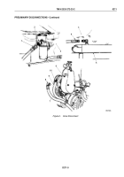
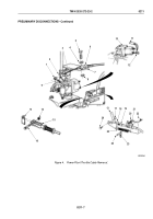
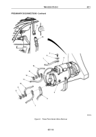
Remove screw (Figure 4, Item 9) and connector (Figure 4, Item 1) from emergency stop cable
(Figure
4,
Item
3).
16.
Remove nut (Figure 4, Item 8), screw (Figure 4, Item 5), washer (Figure 4, Item 4), and clamp
(Figure
4,
Item
6) from bracket (Figure 4, Item 7), and pull cable (Figure 4, Item 3) through swivel block
(Figure
4, Item 2).
17.
Install connector (Figure 4, Item 1) on cable (Figure 4, Item 3) with screw (Figure 4, Item 9).
18.
Install clamp (Figure 4, Item 6) on bracket (Figure 4, Item 7) with screw (Figure 4, Item 5), washer
(Figure
4,
Item 4), and nut (Figure 4, Item 8).
19.
Remove nut (Figure 4, Item 12) and two wires (Figure 4, Item 11) from fuel shutoff solenoid
(Figure
4,
Item
10).
20.
Remove locknut (Figure 4, Item 14), screw (Figure 4, Item 16), and accelerator rod (Figure 4, Item 15) from
throttle lever (Figure 4, Item 13), and tie accelerator rod clear of engine. Discard locknut.
21.
Remove locknut (Figure 4, Item 17), screw (Figure 4, Item 26), and link (Figure 4, Item 18) from throttle lever
(Figure 4, Item 13). Discard locknut.
22.
Remove return spring (Figure 4, Item 25), two nuts (Figure 4, Item 22), screws (Figure 4, Item 24), cable clamp
(Figure 4, Item 23), and shim (Figure 4, Item 21) from fuel primer pump bracket (Figure 4, Item 20).
23.
Remove modulator cable (Figure 4, Item 19) from fuel primer pump bracket (Figure 4, Item 20), and tie cable
clear of engine.
TM 9-2320-272-23-2
0211
0211-6
Back to Top


