TM-9-2320-272-23-2 - Page 459 of 1417
INSTALLATION - Continued
NOTE
Perform Step (3) for late model engines.
3.
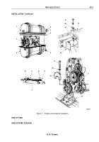
Install breather tube (Figure 4, Item 8) on breather (Figure 4, Item 7) and elbow (Figure 4, Item 10) and tighten
two hose clamps (Figure 4, Item 9).
4.
Install flywheel housing (Figure 4, Item 13) on rear trunnion mount (Figure 4, Item 14) with two washers
(Figure
4,
Item
16), lockwashers (Figure 4, Item 15), and screws (Figure 4, Item 12).
5.
Remove utility chain and lifting device from two engine lifting eyes (Figure 3, Item 1).
6.
Install trunnion cap (Figure 4, Item 19) on front trunnion mount (Figure 4, Item 18) and engine
(Figure
4,
Item
7) with two lockwashers (Figure 4, Item 20) and screws (Figure 4, Item 17).
NOTE
Ensure seal is seated in groove on container lid.
7.
Install upper container section (Figure 4, Item 1) and seal (Figure 4, Item 4) on lower container section
(Figure
4,
Item
6) with 42 screws (Figure 4, Item 5), lockwashers (Figure 4, Item 3), and nuts
(Figure
4,
Item
2). Tighten nuts to 85 to 105 lb-ft (115 to 142 N·m).
TM 9-2320-272-23-2
0212
0212-6
Back to Top

