TM-9-2320-272-23-2 - Page 449 of 1417
INSTALLATION - Continued
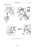
67.
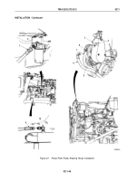
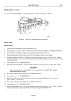
Connect wire (Figure 29, Item 1) to water temperature sending unit (Figure 29, Item 2).
M9254DAA
2
1
Figure 29.
Power Plant Temperature Wiring Installation.
END OF TASK
INSTALLATION
1.
Inspect engine coolant and oil levels (TM 9-2320-272-10).
2.
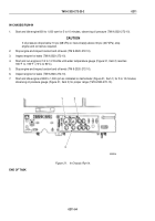
Pull emergency stop control (Figure 30, Item 4) out all the way to prevent engine from starting while priming.
3.
Crank engine until oil pressure registers on oil pressure gauge (Figure 30, Item 3).
4.
Push emergency stop control (Figure 30, Item 4) in all the way and reset fuel pump lever.
5.
Start and run engine at 1,000 to 2,000 rpm as indicated on tachometer (Figure 30, Item 1) for 30 minutes,
observing oil pressure (Figure 30, Item 3) and water temperature (Figure 30, Item 2) gauges for proper ranges
(TM 9-2320-272-10).
6.
Inspect engine for leaks (TM 9-2320-272-10).
7.
Start and idle engine at 800 to 1,000 rpm for 5 to 10 minutes, observing oil pressure (TM 9-2320-272-10).
CAUTION
If oil pressure drops below 10 psi (68 kPa) or rises sharply above 30 psi (207 kPa), stop the
engine and correct as required.
8.
Stop engine and inspect coolant and oil levels (TM 9-2320-272-10).
9.
Inspect engine for leaks (TM 9-2320-272-10).
10.
Start and run engine at 1/4 to 1/2 throttle until water temperature gauge (Figure 30, Item 2) reaches
165°F
to
195°F
(73°C to 90°C).
11.
Stop engine and inspect coolant and oil levels (TM 9-2320-272-10).
12.
Inspect engine for leaks (TM 9-2320-272-10).
13.
Start and idle engine at 800 to 1,000 rpm as indicated on tachometer (Figure 30, Item 1) for 5 to 10 minutes,
observing oil pressure gauge (Figure 30, Item 3) for proper range (TM 9-2320-272-10).
TM 9-2320-272-23-2
0211
0211-52
Back to Top

