TM-9-2320-272-23-2 - Page 695 of 1417
CLEANING AND INSPECTION
1.
For General Cleaning Instructions, refer to (Volume 5, WP
0819).
2.
For General Inspection Instructions, refer to (Volume 5, WP
0819).
3.
Inspect fuel injection tubes for cracks or dents. If cracked or dented, replace fuel injection tubes.
4.
Inspect fuel manifold for cracks or dents. If cracked or dented, replace fuel manifold.
5.
Replace all parts failing inspection.
END OF TASK
INSTALLATION
CAUTION
•
Injector tubes deliver fuel at high pressure causing them to expand and contract. Ensure
injector tubes are securely clamped and routed so they do not come in contact with each
other or any engine component. Failure to do so may result in premature injector
tube
failure.
•
Injector tubes must be installed in correct positions as tagged. Failure to do so may result
in damage to tubes and engine malfunction.
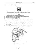
1.
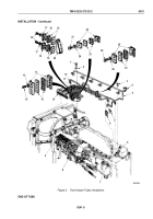
Install four isolators (Figure 2, Item 19), brace (Figure 2, Item 20), and two tube braces (Figure 2, Item 18) on
six fuel injector tubes (Figure 2, Item 11) with four washers (Figure 2, Item 17) and screws (Figure 2, Item 16).
Finger tighten screws.
2.
Install two isolators (Figure 2, Item 14) and tube braces (Figure 2, Item 13) on fuel injector tubes
(Figure
2,
Item
11) with four washers (Figure 2, Item 15) and screws (Figure 2, Item 12). Finger tighten screws.
3.
Install two isolators (Figure 2, Item 23) and tube braces (Figure 2, Item 22) on fuel injector tubes
(Figure
2,
Item
11) with washer (Figure 2, Item 24) and screw (Figure 2, Item 21). Finger tighten screw.
4.
Install two isolators (Figure 2, Item 27) and tube braces (Figure 2, Item 26) on injector tubes
(Figure
2,
Item
11) with two washers (Figure 2, Item 28) and screws (Figure 2, Item 25). Finger tighten screws.
5.
Install six fuel injector tubes (Figure 2, Item 11) on cylinder head (Figure 2, Item 8) with washer
(Figure
2,
Item
2) and screw (Figure 2, Item 1).
6.
Position six fuel injector tubes (Figure 2, Item 11) on fuel injection pump (Figure 2, Item 9) and fuel injectors
(Figure 2, Item 6).
7.
Connect six fuel tube nuts (Figure 2, Item 10) to fuel injection pump (Figure 2, Item 9).
8.
Connect six fuel tube nuts (Figure 2, Item 10) to fuel injectors (Figure 2, Item 6).
9.
Tighten two screws (Figure 2, Item 25), screw (Figure 2, Item 21), four screws (Figure 2, Item 12) and screws
(Figure 2, Item 16).
NOTE
Banjo seals must face toward fuel injectors to allow installation of valve cover.
10.
Install fuel manifold (Figure 2, Item 5) and seven banjo seals (Figure 2, Item 4) on six fuel injectors
(Figure
2,
Item
6) and fuel supply tube (Figure 2, Item 7) with seven screws (Figure 2, Item 3).
TM 9-2320-272-23-2
0241
0241-4
Back to Top

