TM-9-2320-272-23-2 - Page 686 of 1417
INSTALLATION - Continued
M9650DAA
12
1
2
4
5
6
7
8
10
11
3
9
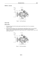
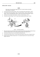
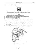
Figure 8.
Fuel Pump Installation.
NOTE
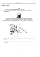
Steps (11) through (13) apply to fuel pump with VS governor only.
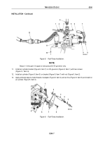
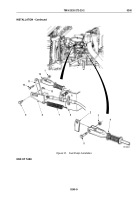
11.
Install air cylinder bracket (Figure 9, Item 7) on VS governor (Figure 9, Item 1) with two screws
(Figure
9,
Item
6).
12.
Install air cylinder (Figure 9, Item 3) on bracket (Figure 9, Item 7) with nut (Figure 9, Item 2).
13.
Apply antiseize tape to male threads of adapter (Figure 9, Item 4) and air line (Figure 9, Item 5) and install on
air cylinder (Figure 9, Item 3).
M9653DAA
5
7
6
8
4
3
2
1
Figure 9.
Fuel Pump Installation.
TM 9-2320-272-23-2
0240
0240-7
Back to Top

