TM-9-2320-272-23-2 - Page 683 of 1417
REMOVAL - Continued
NOTE
Steps (11) through (13) apply to fuel pump with VS governor only.
11.
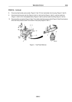
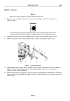
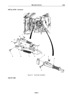
Remove two screws (Figure 4, Item 6) and air cylinder bracket (Figure 4, Item 7) from VS governor
(Figure
4,
Item 1).
WARNING
Do not disconnect air lines or hoses before draining air reservoirs. Small parts under pressure
may shoot out with high velocity. Failure to comply may result in injury or death to personnel.
12.
Remove air line (Figure 4, Item 5) and adapter (Figure 4, Item 4) from air cylinder (Figure 4, Item 3).
13.
Remove nut (Figure 4, Item 2) and air cylinder (Figure 4, Item 3) from bracket (Figure 4, Item 7).
M9652DAA
5
7
6
8
4
3
2
1
Figure 4.
Fuel Pump Removal.
14.
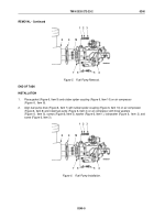
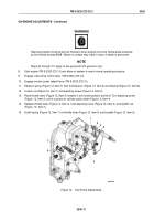
Remove three screws (Figure 5, Item 5), washers (Figure 5, Item 6), screw (Figure 5, Item 3), lockwasher
(Figure 5, Item 2), washer (Figure 5, Item 1), and fuel pump (Figure 5, Item 4) from air compressor
(Figure
5,
Item 8). Discard lockwasher.
15.
Remove rubber spider coupling (Figure 5, Item 10) and fuel pump gasket (Figure 5, Item 9) from air compressor
(Figure 5, Item 8). Discard gasket. Clean gasket remains from mating surfaces of air compressor and rubber
spider coupling.
TM 9-2320-272-23-2
0240
0240-4
Back to Top

