TM-9-2320-272-23-2 - Page 685 of 1417
INSTALLATION - Continued
NOTE
Squirt clean oil into pump through adapter elbow hole. This aids fuel pickup and provides
pump lubrication on initial start.
3.
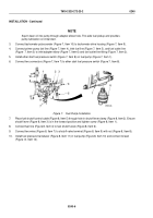
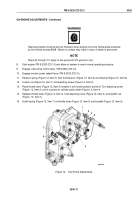
Connect tachometer pulse sender (Figure 7, Item 10) to tachometer drive housing (Figure 7, Item 9).
4.
Connect primer pump fuel line (Figure 7, Item 4), inlet fuel line (Figure 7, Item 5), and fuel outlet line
(Figure
7, Item 3) to inlet adapter elbow (Figure 7, Item 6) and fuel outlet line fitting (Figure 7, Item 2).
5.
Install ether start fuel pressure switch (Figure 7, Item 8) on fuel pump (Figure 7, Item 1).
6.
Connect two connectors (Figure 7, Item 7) to ether start fuel pressure switch (Figure 7, Item 8).
M7141DAA
1
2
8
3
4
5
6
1
7
8
9
10
Figure 7.
Fuel Pump Installation.
7.
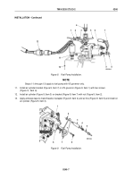
Place fuel shutoff control cable (Figure 8, Item 5) through hole in shutoff lever clamp (Figure 8, Item 2). Ensure
shutoff lever (Figure 8, Item 3) is in the forward position and tighten screw (Figure 8, Item 1).
8.
Connect fuel line (Figure 8, Item 4) to fuel shutoff valve (Figure 8, Item 6).
9.
Connect two wires (Figure 8, Item 7) to shutoff valve terminal (Figure 8, Item 9) with nut (Figure 8, Item 8).
10.
Install fuel pressure transducer (Figure 8, Item 11) in fuel pump (Figure 8, Item 10) and connect to lead
(Figure
8,
Item 12).
TM 9-2320-272-23-2
0240
0240-6
Back to Top


