TM-9-2320-272-23-2 - Page 711 of 1417
INSTALLATION - Continued
19.
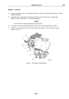
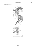
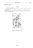
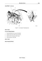
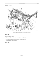
Install fuel supply tube (Figure 9, Item 3) on cylinder head (Figure 9, Item 9) with two connector washers
(Figure
9,
Item
4), bushing (Figure 9, Item 5), and screw (Figure 9, Item 6).
20.
Install fuel return tube (Figure 9, Item 3) on fuel injection pump (Figure 9, Item 23) with two connector washers
(Figure 9, Item 2) and screw (Figure 9, Item 1).
21.
Connect six fuel injector fuel lines (Figure 9, Item 24) to fuel injection pump (Figure 9, Item 23).
22.
Install fuel return hose (Figure 9, Item 20) on fuel injection pump fuel return nipple (Figure 9, Item 22) with
clamp (Figure 9, Item 21).
23.
Install lockwasher (Figure 9, Item 16) and ball joint (Figure 9, Item 17) on throttle lever (Figure 9, Item 15).
24.
Compress socket (Figure 9, Item 18) and install accelerator linkage (Figure 9, Item 12) on ball joint
(Figure
9,
Item
17).
25.
Place modulator control cable (Figure 9, Item 13) on throttle lever (Figure 9, Item 15).
26.
Install washer (Figure 9, Item 11) and cotter pin (Figure 9, Item 10) on link pin (Figure 9, Item 14).
27.
Install throttle connector (Figure 9, Item 26) in cable pivot (Figure 9, Item 27).
28.
Install control cable (Figure 9, Item 8) in throttle connector (Figure 9, Item 26) and install screw
(Figure
9,
Item
25).
29.
Install cable pivot (Figure 9, Item 27) on shutoff valve lever (Figure 9, Item 19) with washer
(Figure
9,
Item
31) and cotter pin (Figure 9, Item 30).
30.
Install control cable (Figure 9, Item 8) on fuel pump bracket (Figure 9, Item 28) with clamp (Figure
9,
Item
7)
and screw (Figure 9, Item 29).
TM 9-2320-272-23-2
0242
0242-14
Back to Top


