TM-9-2320-272-23-3 - Page 105 of 1469
REMOVAL - Continued
9.
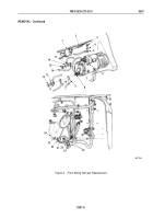
Disconnect wire (Figure 2, Item 2) from oil pressure sending unit (Figure 2, Item 1).
10.
Remove screw assembled washer (Figure 2, Item 3), washer (Figure 2, Item 4), and wire (Figure 2, Item 5)
from starter solenoid (Figure 2, Item 6).
NOTE
M936 vehicles may not have lockwasher.
11.
Remove nut (Figure 2, Item 15), lockwasher (Figure 2, Item 16), wire (Figure 2, Item 17), and wire
(Figure
2,
Item
14) from solenoid post (Figure 2, Item 7). Discard lockwasher.
12.
Place wire (Figure 2, Item 17) on post (Figure 2, Item 7) and secure with nut (Figure 2, Item 15).
13.
Remove nut (Figure 2, Item 12), lockwasher (Figure 2, Item 13), wire (Figure 2, Item 11), and wire
(Figure
2,
Item
10) from starter motor terminal (Figure 2, Item 8). Discard lockwasher.
14.
Place wire (Figure 2, Item 11) and grounding sleeve (Figure 2, Item 9) on post (Figure 2, Item 8) and secure
with nut (Figure 2, Item 12).
15.
Remove screw assembled washer (Figure 2, Item 20), wire (Figure 2, Item 21), ground strap
(Figure
2,
Item
22), and lockwasher (Figure 2, Item 23) from intake manifold (Figure 2, Item 24).
Discard
lockwasher.
16.
Disconnect connectors (Figure 2, Items 18 and 19).
TM 9-2320-272-23-3
0357
0357-4
Back to Top


