TM-9-2320-272-23-3 - Page 1081 of 1469
INSTALLATION
1.
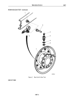
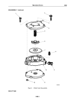
Apply a thin coat of sealing compound to mating surfaces of spindle (Figure 2, Item 9) and adapter ring
(Figure
2,
Item
10), and install adapter ring on spindle.
NOTE
Wrap all male threads with antiseize tape before installation.
2.
Install o-ring (Figure 2, Item 11) and elbow (Figure 2, Item 12) on adapter ring (Figure 2, Item 10).
3.
Insert tube (Figure 2, Item 8) through hole in dust shield (Figure 2, Item 3) and install tube on elbow
(Figure
2,
Item
12) with nut (Figure 2, Item 13).
4.
Install o-ring (Figure 2, Item 4) and air manifold (Figure 2, Item 7) on dust shield (Figure 2, Item 3) with two
washers (Figure 2, Item 2) and screws (Figure 2, Item 1).
5.
Install fitting (Figure 2, Item 6) on air manifold (Figure 2, Item 7).
6.
Connect air line (Figure 2, Item 5) to fitting (Figure 2, Item 6).
TM 9-2320-272-23-3
0488
0488-4
Back to Top


