TM-9-2320-272-23-3 - Page 1087 of 1469
ASSEMBLY
NOTE
Wrap male threads with antiseize tape before installation.
1.
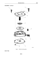
Install tank valve (Figure 2, Item 8) on valve body (Figure 2, Item 10).
2.
Install ball (Figure 2, Item 3) in cover (Figure 2, Item 4).
3.
Position base (Figure 2, Item 11), diaphragm (Figure 2, Item 7), plug (Figure 2, Item 6), spring
(Figure
2,
Item
5) and cover (Figure 2, Item 4) on valve body (Figure 2, Item 10). Carefully hold in place.
4.
Install three screw assembled lockwashers (Figure 2, Item 2), screw assembled lockwasher
(Figure
2,
Item
1), and four nuts (Figure 2, Item 12) on cover (Figure 2, Item 4), valve body
(Figure
2,
Item
10), and base.
5.
Install filter (Figure 2, Item 9) in valve body (Figure 2, Item 10).
TM 9-2320-272-23-3
0489
0489-4
Back to Top

