TM-9-2320-272-23-3 - Page 139 of 1469
INSTALLATION - Continued
55.
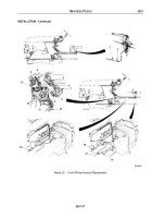
Connect two connectors (Figure 21, Item 11) of alternator (Figure 21, Item 10) wiring.
56.
Install wire (Figure 21, Item 9) on alternator (Figure 21, Item 10) with washer (Figure 21, Item 8), lockwasher
(Figure 21, Item 7), and nut (Figure 21, Item 6). Tighten nut 20 to 25 lb-in. (2 to 3 N·m).
57.
Install wire (Figure 21, Item 13) on alternator (Figure 21, Item 10) with washer (Figure 21, Item 17), lockwasher
(Figure 21, Item 18), and nut (Figure 21, Item 19). Tighten nut 45 to 55 lb-in. (5 to 6 N·m).
58.
Install wire retaining strap (Figure 21, Item 1) over wire (Figure 21, Item 11) and on alternator
(Figure
21,
Item
10) with two lockwashers (Figure 21, Item 2) and screws (Figure 21, Item 3).
59.
Install wire (Figure 21, Item 14) on alternator (Figure 21, Item 10) with lockwasher (Figure 21, Item 15) and
screw (Figure 21, Item 16). Tighten screw 82 to 102 lb-in. (9 to 12 N·m).
60.
Apply silicone rubber adhesive on wires (Figure 21, Items 9 and 13) and install cover (Figure 21, Item 4) on
alternator (Figure
21,
Item
10) with two screw assembled lockwashers (Figure 21, Item 5).
NOTE
Two tiedown straps go over wires on inside right frame rail.
61.
Install three tiedown straps (Figure 21, Item 12).
62.
Connect wire (Figure 21, Item 25) to transorb diode coupling assembly wire (Figure 21, Item 22).
63.
Connect wires (Figure 21, Items 26 and 27) to horn solenoid (Figure 21, Item 28).
64.
Install four tiedown straps (Figure 21, Item 24) on rear of harness.
65.
Install three cable clamps (Figure 21, Item 21) on firewall (Figure 21, Item 20) with three screws
(Figure
21,
Item
23).
TM 9-2320-272-23-3
0357
0357-38
Back to Top

