TM-9-2320-272-23-3 - Page 201 of 1469
REMOVAL - Continued
NOTE
Perform Step (24) for M931/A1/A2 and M932/A1/A2 vehicles only.
24.
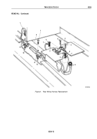
Remove locknut (Figure 8, Item 4), screw (Figure 8, Item 2), clamp (Figure 8, Item 3), two ground wires
(Figure
8, Item 6), and lockwasher (Figure 8, Item 5) from rear crossmember frame rail (Figure 8, Item 1).
Discard locknut and lockwasher.
NOTE
Perform Step (25) for all vehicles except M931/A1/A2 and M932/A1/A2 vehicles.
25.
Remove locknut (Figure 8, Item 11), screw (Figure 8, Item 7), two ground wires (Figure 8, Item 10), and
lockwasher (Figure 8, Item 9) from rear frame rail (Figure 8, Item 8). Discard locknut and lockwasher.
NOTE
Receptacle cover must be lifted and held open to remove top two screws.
26.
Remove four locknuts (Figure 8, Item 15), screws (Figure 8, Item 17), receptacle cover (Figure 8, Item 12),
and trailer cable receptacle (Figure 8, Item 13) from rear crossmember frame (Figure 8, Item 8).
Discard
locknuts.
27.
Pull rear portions of rear wiring harness (Figure 8, Item 16) through hole (Figure 8, Item 14) in rear crossmember
frame (Figure 8, Item 8).
TM 9-2320-272-23-3
0359
0359-16
Back to Top


