TM-9-2320-272-23-3 - Page 797 of 1469
INSTALLATION
CAUTION
Open-end wrench must be used to anchor tank boss fittings when connecting or
disconnecting associated fittings. Damage to tank bosses may result if open-end wrench is
not used.
NOTE
•
If new reservoir is being installed, fittings from oil reservoir may be used. Fittings must
be cleaned and inspected for cracks and stripped threads.
•
Apply sealant to all male pipe threads before installation.
1.
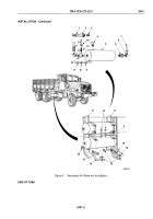
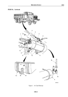
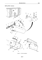
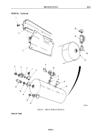
Install adapters (Figure 3, Item 18) and (Figure 3, Item 19) on supply tank (Figure 3, Item 17).
2.
Install nipple (Figure 3, Item 20), tee (Figure 3, Item 7), reducer (Figure 3, Item 8), nipple (Figure 3, Item 9),
relief valve (Figure 3, Item 11), elbow (Figure 3, Item 10), shutoff valve (Figure 3, Item 6), and elbow
(Figure
3,
Item
5) on supply tank (Figure 3, Item 17).
3.
Install elbow (Figure 3, Item 16), nipple (Figure 3, Item 15), shutoff valve (Figure 3, Item 14), and adapter
(Figure 3, Item 13) on supply tank (Figure 3, Item 17).
4.
Install elbow (Figure 3, Item 12) on supply tank (Figure 3, Item 17).
5.
Install tee (Figure 3, Item 26), reducer (Figure 3, Item 24), safety valve (Figure 3, Item 23), and elbow
(Figure
3,
Item
25) on supply tank (Figure 3, Item 17).
6.
Install two support brackets (Figure 3, Item 4) on frame braces (Figure 3, Item 1) with four screws
(Figure
3,
Item
2) and locknuts (Figure 3, Item 3).
7.
Install supply tank (Figure 3, Item 17) on two support brackets (Figure 3, Item 4) with two U-bolts
(Figure
3,
Item
22) and four locknuts (Figure 3, Item 21).
NOTE
Perform Steps (8) through (11) for M934/A1/A2 vehicles.
8.
Install elbow (Figure 3, Item 30) on supply tank (Figure 3, Item 17).
9.
Install elbow (Figure 3, Item 29), shutoff valve (Figure 3, Item 28), and adapter (Figure 3, Item 27) on supply
tank (Figure 3, Item 17).
10.
Install support plate (Figure 3, Item 31) on frame (Figure 3, Item 35) with four screws (Figure 3, Item 34).
11.
Install supply tank (Figure 3, Item 17) on support plate (Figure 3, Item 31) with two U-bolts (Figure 3, Item 33)
and four locknuts (Figure 3, Item 32).
TM 9-2320-272-23-3
0442
0442-6
Back to Top

