TM-9-2320-272-23-3 - Page 805 of 1469
REMOVAL - Continued
8.
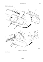
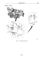
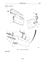
Remove four screws (Figure 2, Item 1) and support plate (Figure 2, Item 3) from frame (Figure 2, Item 2).
9.
Remove elbow (Figure 2, Item 20), shutoff valve (Figure 2, Item 21), and elbow (Figure 2, Item 22) from supply
tank (Figure 2, Item 14).
10.
Remove elbow (Figure 2, Item 13) from supply tank (Figure 2, Item 14).
11.
Remove elbow (Figure 2, Item 9), relief valve (Figure 2, Item 10), nipple (Figure 2, Item 11), and reducer
(Figure
2, Item 12) from supply tank (Figure 2, Item 14).
12.
Remove adapters (Figure 2, Items 15 and 16) from supply tank (Figure 2, Item 14).
13.
Remove adapters (Figure 2, Items 4 and 7), safety valve (Figure 2, Item 19), reducer (Figure 2, Item 18), shutoff
valve (Figure 2, Item 5), tees (Figure 2, Items 8 and 17), and nipple (Figure 2, Item 6) from supply tank
(Figure
2, Item 14).
TM 9-2320-272-23-3
0443
0443-4
Back to Top

