TM-9-2320-272-23-3 - Page 809 of 1469
INSTALLATION - Continued
7.
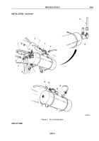
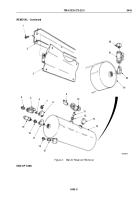
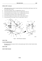
Install supply tank (Figure 4, Item 6) on support plate (Figure 4, Item 9) with two U-bolts (Figure 4, Item 7) and
four locknuts (Figure 4, Item 8).
8.
Connect drain line (Figure 4, Item 11) to adapter (Figure 4, Item 10).
9.
Connect secondary tank air line (Figure 4, Item 13) to adapter (Figure 4, Item 12).
10.
Connect supply tank input air line (Figure 4, Item 1) to adapter (Figure 4, Item 14).
11.
Connect auxiliary air line (Figure 4, Item 2) to elbow (Figure 4, Item 3).
12.
Connect trailer emergency air line (Figure 4, Item 4) to elbow (Figure 4, Item 5).
13.
Connect primary tank air line (Figure 4, Item 15) to elbow (Figure 4, Item 16).
2
3
4
5
6
7
8
9
7
8
10
11
12
13
14
1
15
16
M6228DAA
Figure 4.
Wet Air Reservoir Installation.
END OF TASK
FOLLOW-ON MAINTENANCE
Start engine and allow air pressure to build to normal operating range. Check for air leaks. Road test vehicle.
(TM 9-2320-272-10)
END OF TASK
END OF WORK PACKAGE
TM 9-2320-272-23-3
0443
0443-8
Back to Top

