TM-9-2320-272-23-3 - Page 807 of 1469
INSTALLATION
NOTE
•
If new reservoir is being installed, fittings from old reservoir may be used. Fittings must
be cleaned and inspected for cracks and stripped threads.
•
Wrap male pipe threads with antiseize tape before installation.
1.
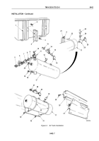
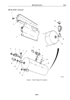
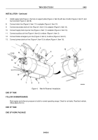
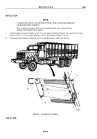
Install nipple (Figure 3, Item 6), tees (Figure 3, Items 8 and 17), shutoff valve (Figure 3, Item 5), reducer
(Figure
3, Item 18), safety valve (Figure 3, Item 19), and adapters (Figure 3, Items 4 and 7) on supply tank
(Figure 3, Item 14).
2.
Install adapters (Figure 3, Items 15 and 16) on supply tank (Figure 3, Item 14).
3.
Install reducer (Figure 3, Item 12), nipple (Figure 3, Item 11), relief valve (Figure 3, Item 10), and elbow
(Figure
3, Item 9) on supply tank (Figure 3, Item 14).
4.
Install elbow (Figure 3, Item 13) on supply tank (Figure 3, Item 14).
5.
Install elbow (Figure 3, Item 22), shutoff valve (Figure 3, Item 21), and elbow (Figure 3, Item 20) on supply
tank (Figure 3, Item 14).
6.
Install support plate (Figure 3, Item 3) on frame (Figure 3, Item 2) with four screws (Figure 3, Item 1).
TM 9-2320-272-23-3
0443
0443-6
Back to Top

