TM-9-2320-272-23-3 - Page 853 of 1469
FRONT AIR COUPLINGS INSTALLATION
NOTE
•
Fittings must be cleaned and inspected for cracks and stripped threads.
•
Apply sealant to all male pipe threads before installation.
•
Perform Step (1) for emergency coupling on left side of vehicle.
1.
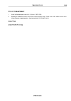
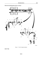
Install elbow (Figure 4, Item 3) in valve (Figure 4, Item 13).
NOTE
Perform Step (2) for service coupling on right side of vehicle.
2.
Install elbow (Figure 4, Item 3) in air coupling (Figure 4, Item 2) and place air coupling in soft-jawed vise.
3.
Install adapter (Figure 4, Item 4) in elbow (Figure 4, Item 3) and remove air coupling (Figure 4, Item 2)
from
vise.
4.
Install identification plate (Figure 4, Item 6), bracket (Figure 4, Item 5), and adapter (Figure 4, Item 4) in frame
rail (Figure 4, Item 7) with lockwasher (Figure 4, Item 8) and nut (Figure 4, Item 9).
5.
Install elbow (Figure 4, Item 10) on adapter (Figure 4, Item 4).
6.
Connect air line (Figure 4, Item 11) to elbow (Figure 4, Item 10).
NOTE
Perform Steps (7) and (8) for emergency coupling on left side of vehicle.
7.
Install pipe nipple (Figure 4, Item 14) in valve (Figure 4, Item 13).
8.
Install air coupling (Figure 4, Item 2) on pipe nipple (Figure 4, Item 14).
9.
Install dummy couplings (Figure 4, Item 15) and (Figure 4, Item 4) and S-hook (Figure 4, Item 12) on air coupling
(Figure 4, Item 2) and bracket (Figure 4, Item 5).
TM 9-2320-272-23-3
0450
0450-8
Back to Top

