TM-9-2320-272-23-3 - Page 889 of 1469
REMOVAL
WARNING
Do not disconnect air lines or hoses before draining air reservoirs. Small parts under pressure
may shoot out with high velocity. Failure to comply may result in injury or death to personnel.
CAUTION
When disconnecting air lines and hoses, plug all openings to prevent dirt from entering and
causing damage to internal parts. Remove all plugs prior to installation.
NOTE
•
Tag lines and fittings for installation.
•
Mark fitting direction for installation.
1.
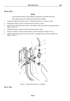
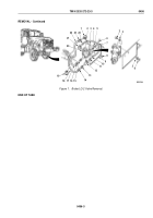
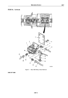
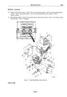
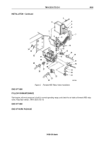
Loosen nut (Figure 1, Item 10) and disconnect yellow channel connector (Figure 1, Item 11) from rear ABS
relay valve (Figure 1, Item 1).
2.
Loosen nut (Figure 1, Item 13) and remove air line (Figure 1, Item 12) from elbow (Figure 1, Item 14) on control
port (Figure 1, Item 2).
3.
Loosen nut (Figure 1, Item 16) and remove air line (Figure 1, Item 15) from adapter (Figure 1, Item 17) on
supply port (Figure 1, Item 18).
4.
Loosen nut (Figure 1, Item 20) and remove air line (Figure 1, Item 21) from adapter (Figure 1, Item 19) on
delivery port (Figure 1, Item 22).
5.
Loosen nut (Figure 1, Item 7) and remove air line (Figure 1, Item 8) from elbow (Figure 1, Item 6) on delivery
port (Figure 1, Item 9).
6.
Remove two locknuts (Figure 1, Item 4), washers (Figure 1, Item 5), and rear ABS relay valve
(Figure
1,
Item
1) from bracket (Figure 1, Item 3). Discard locknuts.
7.
Remove adapter (Figure 1, Item 17) from supply port (Figure 1, Item 18) on rear ABS relay valve
(Figure
1,
Item
1).
8.
Remove adapter (Figure 1, Item 19) from delivery port (Figure 1, Item 22) on rear ABS relay valve
(Figure
1,
Item
1).
9.
Remove elbow (Figure 1, Item 6) from delivery port (Figure 1, Item 9) on rear ABS relay valve
(Figure
1,
Item
1).
10.
Remove elbow (Figure 1, Item 14) from control port (Figure 1, Item 2) on rear ABS relay valve
(Figure
1,
Item
1).
TM 9-2320-272-23-3
0457
0457-2
Back to Top

