TM-9-2320-272-23-3 - Page 897 of 1469
INSTALLATION
1.
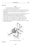
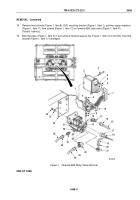
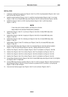
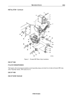
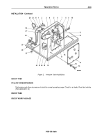
If removed, install harness support clip (Figure 2, Item 10) on ECU mounting bracket (Figure 2, Item 1) and
bend out two tabs (Figure 2, Item 9).
2.
Install two spacer washers (Figure 2, Item 11) and ECU mounting bracket (Figure 2, Item 1) on screws
(Figure
2,
Item
12) on forward ABS relay valve (Figure 2, Item 31) with two locknuts (Figure 2, Item 8).
3.
Install ECU (Figure 2, Item 2) on ECU mounting bracket (Figure 2, Item 1) with three screws
(Figure
2,
Item
3).
NOTE
•
If new relay valve is being installed, use fittings from old valve.
•
Apply sealant to all male pipe threads before installation.
4.
Install elbow (Figure 2, Item 21) in control port (Figure 2, Item 26) on forward ABS relay valve
(Figure
2,
Item
31).
5.
Install elbow (Figure 2, Item 22) in supply port (Figure 2, Item 25) on forward ABS relay valve
(Figure
2,
Item
31).
6.
Install elbow (Figure 2, Item 13) in delivery port (Figure 2, Item 16) on forward ABS relay valve
(Figure
2,
Item
31).
7.
Install adapter (Figure 2, Item 27) in delivery port (Figure 2, Item 30) on forward ABS relay valve
(Figure
2,
Item
31).
8.
Install forward ABS relay valve (Figure 2, Item 31) on bracket (Figure 2, Item 32) with two washers
(Figure
2,
Item
33) and locknuts (Figure 2, Item 34). Tighten locknuts 33 lb-ft (45 N·m).
9.
Install air line (Figure 2, Item 29) on adapter (Figure 2, Item 27) and tighten nut (Figure 2, Item 28).
10.
Install air line (Figure 2, Item 15) on elbow (Figure 2, Item 13) and tighten nut (Figure 2, Item 14).
11.
Install air line (Figure 2, Item 24) on elbow (Figure 2, Item 22) and tighten nut (Figure 2, Item 23).
12.
Install air line (Figure 2, Item 19) on elbow (Figure 2, Item 21) and tighten nut (Figure 2, Item 20).
13.
Connect blue channel connector (Figure 2, Item 18) on forward ABS relay valve (Figure 2, Item 31) and tighten
nut (Figure 2, Item 17) finger tight.
14.
Connect ABS wiring harness connector (Figure 2, Item 7) on ECU connector (Figure 2, Item 6) and listen for
the locking tabs (Figure 2, Item 4) to click as connector is pushed into ECU connector. Lock spring clip
(Figure
2,
Item
5) over connector.
15.
Close and lock harness support clip (Figure 2, Item 10) over connector (Figure 2, Item 7).
TM 9-2320-272-23-3
0458
0458-4
Back to Top


