TM-9-2320-272-23-3 - Page 891 of 1469
INSTALLATION
NOTE
•
If new relay valve is being installed, use fittings from old valve.
•
Apply sealant to all male pipe threads before installation.
1.
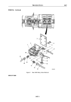
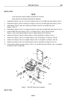
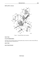
Install elbow (Figure 2, Item 14) in control port (Figure 2, Item 2) on rear ABS relay valve (Figure 2, Item 1).
2.
Install elbow (Figure 2, Item 6) in delivery port (Figure 2, Item 9) on rear ABS relay valve (Figure 2, Item 1).
3.
Install adapter (Figure 2, Item 19) in delivery port (Figure 2, Item 22) on rear ABS relay valve
(Figure
2,
Item
1).
4.
Install adapter (Figure 2, Item 17) in supply port (Figure 2, Item 18) on rear ABS relay valve (Figure 2, Item 1).
5.
Install rear ABS relay valve (Figure 2, Item 1) on bracket (Figure 2, Item 3) with two washers
(Figure
2,
Item
5) and locknuts (Figure 2, Item 4). Tighten locknuts 33 lb-ft (45 N·m).
6.
Install air line (Figure 2, Item 8) on elbow (Figure 2, Item 6) and tighten nut (Figure 2, Item 7).
7.
Install air line (Figure 2, Item 21) on adapter (Figure 2, Item 19) and tighten nut (Figure 2, Item 20).
8.
Install air line (Figure 2, Item 15) on adapter (Figure 2, Item 17) and tighten nut (Figure 2, Item 16).
9.
Install air line (Figure 2, Item 12) on elbow (Figure 2, Item 14) and tighten nut (Figure 2, Item 13).
10.
Connect yellow channel connector (Figure 2, Item 11) to rear ABS relay valve (Figure 2, Item 1) and tighten
nut (Figure 2, Item 10) finger tight.
3
4
5
6
7
8
9
10
11
12
13
14
15
16
18
19
17
20
22
1
21
2
M9395DAA
Figure 2.
Rear ABS Relay Valve Installation.
END OF TASK
TM 9-2320-272-23-3
0457
0457-4
Back to Top


