TM-9-2320-272-23-3 - Page 903 of 1469
INSTALLATION
NOTE
•
If new inversion valve is being installed, use fittings from old inversion valve.
•
Apply sealing compound to all male pipe threads before installation.
1.
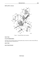
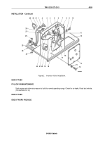
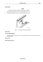
Install exhaust checkvalve (Figure 2, Item 20) in inversion valve (Figure 2, Item 7).
2.
Install adapter (Figure 2, Item 1) in primary balance port (Figure 2, Item 11) on top of inversion valve
(Figure
2, Item 7).
3.
Install elbow (Figure 2, Item 2) in secondary control port (Figure 2, Item 4) on top left side of inversion valve
(Figure 2, Item 7).
4.
Install elbow (Figure 2, Item 3) in supply port (Figure 2, Item 19) on bottom left side of inversion valve
(Figure
2, Item 7).
5.
Install elbow (Figure 2, Item 12) in delivery port (Figure 2, Item 18) on right side of inversion valve
(Figure
2,
Item 7).
6.
Install inversion valve (Figure 2, Item 7) on inside of step box access (Figure 2, Item 8) with two washers
(Figure
2, Item 9), screws (Figure 2, Item 10), washers (Figure 2, Item 6), and locknuts (Figure 2, Item 5).
7.
Install supply air line (Figure 2, Item 22) on bottom left side elbow (Figure 2, Item 3) and tighten nut
(Figure
2,
Item 21).
8.
Install secondary control air line (Figure 2, Item 30) on top left side elbow (Figure 2, Item 2) and tighten nut
(Figure 2, Item 31).
9.
Install delivery air line (Figure 2, Item 17) on right side elbow (Figure 2, Item 12) and tighten nut
(Figure
2,
Item 16).
10.
Install primary balance air line (Figure 2, Item 27) on top adapter (Figure 2, Item 1) and tighten nut
(Figure
2,
Item 28).
11.
Install access box cover (Figure 2, Item 13) on step box access (Figure 2, Item 8) with eight lockwashers
(Figure 2, Item 15) and screws (Figure 2, Item 14).
12.
Install tiedown straps (Figure 2, Item 29) to secure air lines as necessary.
13.
Install clamp (Figure 2, Item 25) with air lines on step brace (Figure 2, Item 24) with screw (Figure 2, Item 26)
and locknut (Figure 2, Item 23).
TM 9-2320-272-23-3
0459
0459-4
Back to Top


