TM-9-2320-272-23-4 - Page 1025 of 1393
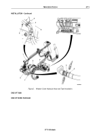
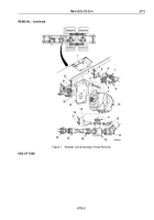
INSTALLATION
1.
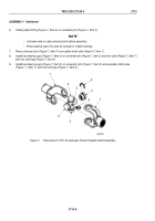
Install mount (Figure 2, Item 19) on crane pump (Figure 2, Item 10) with four lockwashers (Figure 2, Item 2)
and screws (Figure 2, Item 9).
2.
Install o-ring (Figure 2, Item 8) and outlet elbow (Figure 2, Item 6) on crane pump (Figure 2, Item 10) with two
split flanges (Figure 2, Item 5), four lockwashers (Figure 2, Item 3), and screws (Figure 2, Item 4). Tighten
screws 50 to 60 lb-ft (68 to 81 N·m).
3.
Install o-ring (Figure 2, Item 11) and inlet tee (Figure 2, Item 14) on crane pump (Figure 2, Item 10) with two
split flanges (Figure 2, Item 12), four lockwashers (Figure 2, Item 18), and screws (Figure 2, Item 17). Tighten
screws 50 to 60 lb-ft (68 to 81 N·m).
4.
Position shaft of crane pump (Figure 2, Item 10) on driveshaft hub (Figure 2, Item 20).
5.
Position mount (Figure 2, Item 19) with crane pump (Figure 2, Item 10) on bracket (Figure 2, Item 1) and install
with four lockwashers (Figure 2, Item 22) and screws (Figure 2, Item 21).
6.
Connect hose (Figure 2, Item 7) to outlet elbow (Figure 2, Item 6).
7.
Connect hoses (Figure 2, Items 13 and 15) to inlet tee (Figure 2, Item 14).
8.
Connect hose (Figure 2, Item 16) to hose (Figure 2, Item 15).
TM 9-2320-272-23-4
0712
0712-4
Back to Top

