TM-9-2320-272-23-4 - Page 1023 of 1393
REMOVAL
CAUTION
When disconnecting hydraulic hoses and lines, plug all openings to prevent dirt from entering
and causing internal parts damage.
NOTE
•
Tag all hoses and lines for installation.
•
Have drainage container ready to catch oil.
•
Use drain pans to retain leaking/draining fluids. Refer to local procedures and plans for
preventing and responding to fluid spills or leaks. Comply with local regulations when
disposing of clean up material and leaked and spilled fluids.
1.
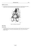
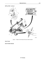
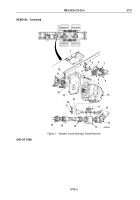
Disconnect hose (Figure 1, Item 16) from hose (Figure 1, Item 15).
2.
Disconnect hoses (Figure 1, Item 13) and (Figure 1, Item 15) from inlet tee (Figure 1, Item 14).
3.
Disconnect hose (Figure 1, Item 7) from outlet elbow (Figure 1, Item 6).
4.
Remove four screws (Figure 1, Item 21), lockwashers (Figure 1, Item 22), and mount (Figure 1, Item 19) with
crane pump (Figure 1, Item 10) from bracket (Figure 1, Item 1). Lower crane pump, and slide from driveshaft
hub (Figure 1, Item 20). Discard lockwashers.
5.
Remove four screws (Figure 1, Item 17), lockwashers (Figure 1, Item 18), two split flanges (Figure 1, Item 12),
inlet tee (Figure 1, Item 14), and o-ring (Figure 1, Item 11) from crane pump (Figure 1, Item 10). Discard
lockwashers and o-ring.
6.
Remove four screws (Figure 1, Item 4), lockwashers (Figure 1, Item 3), two split flanges (Figure 1, Item 5),
outlet elbow (Figure 1, Item 6), and o-ring (Figure 1, Item 8) from crane pump (Figure 1, Item 10). Discard
lockwashers and o-ring.
7.
Remove four screws (Figure 1, Item 9), lockwashers (Figure 1, Item 2), and mount (Figure 1, Item 19) from
crane pump (Figure 1, Item 10). Discard lockwashers.
TM 9-2320-272-23-4
0712
0712-2
Back to Top

