TM-9-2320-272-23-4 - Page 1041 of 1393
REMOVAL
WARNING
•
Never work under dump body until safety braces are properly positioned. Dump body
may suddenly lower. Failure to comply may result in injury or death to personnel.
•
Ensure dump control lever is in the NEUTRAL position and has not moved. Failure to
comply may result in injury or death to personnel.
•
Accidental or intentional introduction of liquid contaminants into the environment is in
violation of state, federal, and military regulations. Refer to local Unit SOP for information
concerning storage, use, and disposal of these liquids. Failure to comply may result in
injury or death to personnel.
•
Do not remove hoses with engine running or start engine with hoses removed. High-
pressure fluids may cause hoses to whip violently and spray randomly. Failure to comply
may result in injury or death to personnel.
NOTE
All hydraulic hoses are removed the same way. This procedure covers dump hoist cylinder
and safety lock hoses only.
1.
Place dump body in raised position (TM 9-2320-272-10).
2.
Place safety braces in proper position (TM 9-2320-272-10).
CAUTION
Plug all hydraulic lines or openings to prevent dirt from entering and damaging components.
NOTE
•
Cross fittings to hoist cylinder hoses must be disconnected from the cross fittings first.
Then hoses can be removed from hoist cylinders.
•
Have drainage container ready to catch oil.
•
Use drain pans to retain leaking/draining fluids. Refer to local procedures and plans for
preventing and responding to fluid spills or leaks. Comply with local regulations when
disposing of clean up material and leaked and spilled fluids.
•
Drain hoses before plugging.
•
Tag hoses for installation.
3.
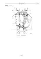
Disconnect four hydraulic hoses (Figure 1, Items 5, 9, 11, and 13) from right cross fitting (Figure 1, Item 10).
4.
Disconnect four hydraulic hoses (Figure 1, Items 4, 6, 8, and 12) from left cross fitting (Figure 1, Item 7).
5.
Disconnect two hydraulic hoses (Figure 1, Items 5 and 11) from right and left cylinder ports
(Figure
1,
Items
1
and
15).
6.
Disconnect two hydraulic hoses (Figure 1, Items 6 and 12) from right and left cylinder ports
(Figure
1,
Items
3
and
14).
7.
Disconnect two hydraulic hoses (Figure 1, Items 4 and 13) from safety lock cylinder (Figure 1, Item 2).
TM 9-2320-272-23-4
0715
0715-2
Back to Top


