TM-9-2320-272-23-4 - Page 1035 of 1393
INSTALLATION
1.
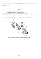
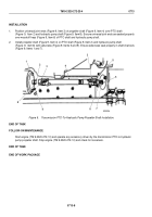
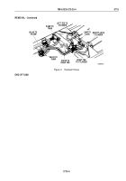
Position universal joint ends (Figure 9, Item 3) of propeller shaft (Figure 9, Item 4) over PTO shaft
(Figure
9,
Item
2) and hydraulic pump shaft (Figure 9, Item 8). Ensure universal joint ends are seated properly
over woodruff keys (Figure 9, Item 6) of PTO shaft and hydraulic pump shaft.
2.
Install propeller shaft (Figure 9, Item 4) on PTO shaft (Figure 9, Item 2) and hydraulic pump shaft
(Figure
9,
Item 8) with setscrews (Figure 9, Items 5 and 9). Ensure setscrews seat properly in shaft channels
(Figure 9, Items 1 and 7).
M5265DAA
6
7
8
5
3
4
1
2
3
6
9
Figure 9.
Transmission PTO-To-Hydraulic Pump Propeller Shaft Installation.
END OF TASK
FOLLOW-ON MAINTENANCE
Start engine (TM 9-2320-272-10) and operate any accessory driven by the transmission PTO-to-hydraulic
pump propeller shaft. Stop engine (TM 9-2320-272-10) and check for looseness.
END OF TASK
END OF WORK PACKAGE
TM 9-2320-272-23-4
0713
0713-8
Back to Top


