TM-9-2320-272-23-4 - Page 1038 of 1393
INSTALLATION
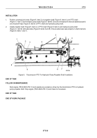
1.
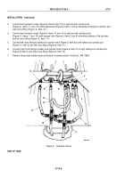
Install driveshaft flange (Figure 2, Item 17) on transfer PTO shaft (Figure 2, Item 2) with washer
(Figure
2,
Item
16) and nut (Figure 2, Item 15).
2.
Raise hydraulic jack enough to position pump shaft (Figure 2, Item 11) and boss (Figure 2, Item 10) of pump
(Figure 2, Item 9) through mount (Figure 2, Item 12). Ensure rear hub of propeller shaft (Figure 2, Item 14)
slides on pump shaft.
3.
Position propeller shaft (Figure 2, Item 14) on PTO shaft (Figure 2, Item 1) with lubrication fitting
(Figure
2,
Item 6) positioned at top.
4.
Install propeller shaft (Figure 2, Item 14) on driveshaft flange (Figure 2, Item 17) with four screws
(Figure
2,
Item 5), lockwashers (Figure 2, Item 4), and nuts (Figure 2, Item 3).
5.
Install pump (Figure 2, Item 9) on mount (Figure 2, Item 12) with four lockwashers (Figure 2, Item 7) and screws
(Figure 2, Item 8). Tighten screws 32 to 40 lb-ft (43 to 54 N·m).
M9050DAA
9
8
7
5
6
4
3
2
1
17
16
15
14
13
12
11
10
Figure 2.
Transfer PTO-to-Hydraulic Pump Propeller Shaft Installation.
END OF TASK
FOLLOW-ON MAINTENANCE
Check operation of crane hydraulic system. (TM 9-2320-272-10)
END OF TASK
END OF WORK PACKAGE
TM 9-2320-272-23-4
0714
0714-3/4 blank
Back to Top

