TM-9-2320-272-23-4 - Page 1121 of 1393
ASSEMBLY - Continued
CAUTION
Clutch collar and shifter must be properly installed to ensure proper PTO operation. Ensure
clutch collar internal splines face away from PTO mounting flange and thick edge of shifter
fork faces shifter shaft.
29.
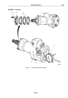
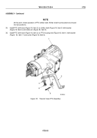
Position splined end (Figure 17, Item 19) of clutch collar (Figure 17, Item 13) over PTO shaft
(Figure 17, Item 18).
30.
Position finger ends (Figure 17, Item 5) of shifter fork (Figure 17, Item 6) in center groove (Figure 17, Item 12)
of clutch collar (Figure 17, Item 13).
31.
Install o-ring (Figure 17, Item 2) on shifter shaft (Figure 17, Item 4).
32.
Place shift shaft (Figure 17, Item 4) through PTO housing bore (Figure 17, Item 11) and fork
(Figure 17, Item 6) and install with setscrew (Figure 17, Item 7) into hole (Figure 17, Item 3). Tighten setscrew
7 to 9 lb-ft (10 to 12 N·m).
33.
Place detent ball (Figure 17, Item 10), spring (Figure 17, Item 9), and dowel (Figure 17, Item 8) into PTO
housing bore (Figure 17, Item 1).
34.
Install cover plate (Figure 17, Item 15) on PTO housing (Figure 17, Item 14) with four washers
(Figure
17,
Item
16) and screws (Figure 17, Item 17). Tighten screws 18 to 24 lb-ft (24 to 32 N·m).
TM 9-2320-272-23-4
0725
0725-18
Back to Top


