TM-9-2320-272-23-4 - Page 1125 of 1393
INSTALLATION
1.
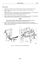
Install oil seal (Figure 21, Item 3) on PTO oil pump drive gear assembly (Figure 21, Item 4).
2.
Install PTO oil pump drive gear assembly (Figure 21, Item 4) on transfer case main input shaft
(Figure 21, Item 2). Align setscrew (Figure 21, Item 1) hole in gear assembly (Figure 21, Item 4) with recess
in main input shaft.
3.
Install setscrew (Figure 21, Item 1) in PTO oil pump drive gear assembly (Figure 21, Item 4) and apply sealing
compound to threads of setscrew. Tighten setscrew 84 to 108 lb-in. (10 to 12 N·m).
4.
Install PTO (Figure 21, Item 10) on transfer case (Figure 21, Item 7) with six washers (Figure 21, Item 6) and
screws (Figure 21, Item 5). Tighten screws 40 to 65 lb-ft (54 to 88 N·m).
NOTE
Wrap male pipe threads with antiseize tape prior to installation.
5.
Install adapter (Figure 21, Item 9) on PTO (Figure 21, Item 10).
6.
Connect transfer case oil return line (Figure 21, Item 8) to adapter (Figure 21, Item 9).
7.
Install PTO clevis (Figure 21, Item 13) on PTO select lever (Figure 21, Item 15) with clevis pin
(Figure 21, Item 14), washer (Figure 21, Item 12), and cotter pin (Figure 21, Item 11).
TM 9-2320-272-23-4
0725
0725-22
Back to Top

