TM-9-2320-272-23-4 - Page 1132 of 1393
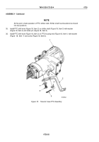
INSTALLATION - Continued
7.
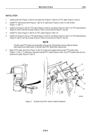
Install PTO clevis (Figure 4, Item 9) on PTO select lever (Figure 4, Item 7) with clevis pin (Figure 4, Item 8)
and cotter pin (Figure 4, Item 6).
8.
Install tiedown straps on PTO cable (Figure 4, Item 10) as required.
7
8
9
10
1
2
3
4
6
5
M9787DAA
Figure 4.
Transfer Case PTO Control Cable Installation.
END OF TASK
FOLLOW-ON MAINTENANCE
Check transfer case PTO for proper operation. (TM 9-2320-272-10)
END OF TASK
END OF WORK PACKAGE
TM 9-2320-272-23-4
0726
0726-5/6 blank
Back to Top


