TM-9-2320-272-23-4 - Page 1135 of 1393
REMOVAL
1.
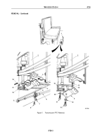
Remove locknut (Figure 1, Item 17) and PTO cable swivel bolt (Figure 1, Item 18) from cross shaft lever
(Figure
1, Item 30). Discard locknut.
2.
Remove two locknuts (Figure 1, Item 16), screws (Figure 1, Item 13), clamp (Figure 1, Item 19), PTO control
cable (Figure 1, Item 20), and shim (Figure 1, Item 15) from bracket (Figure 1, Item 14). Discard locknuts.
NOTE
Assistant will help with Step (3).
3.
Remove four locknuts (Figure 1, Item 12), screws (Figure 1, Item 1), two cross shaft retaining clamps
(Figure 1, Item 3), and shims (Figure 1, Item 4) from cab floor (Figure 1, Item 23). Discard locknuts.
4.
Remove grease fittings (Figure 1, Item 2) from cross shaft retaining clamps (Figure 1, Item 3).
5.
Remove cotter pin (Figure 1, Item 26), washer (Figure 1, Item 28), and brake lock control valve rod
(Figure 1, Item 21) from cross shaft lever (Figure 1, Item 30). Discard cotter pin.
6.
Remove locknut (Figure 1, Item 31) and screw (Figure 1, Item 29) from cross shaft lever (Figure 1, Item 30).
Discard locknut.
NOTE
Assistant will help with Step (7).
7.
Remove six locknuts (Figure 1, Item 22), screws (Figure 1, Item 27), ring seal (Figure 1, Item 25), rubber seal
(Figure 1, Item 24), and cross shaft lever (Figure 1, Item 30) from cab floor (Figure 1, Item 23) and cross shaft
(Figure 1, Item 5). Discard locknuts.
8.
Remove woodruff key (Figure 1, Item 11) and two cross shaft retaining clamps (Figure 1, Item 3) from cross
shaft (Figure 1, Item 5). Discard woodruff key.
9.
Remove locknut (Figure 1, Item 7), washer (Figure 1, Item 8), helical spring (Figure 1, Item 9), and PTO lever
pin (Figure 1, Item 10) from PTO lever (Figure 1, Item 6). Discard locknut.
TM 9-2320-272-23-4
0727
0727-2
Back to Top


