TM-9-2320-272-23-4 - Page 1191 of 1393
RESERVOIR INSTALLATION
NOTE
Wrap all male threads with antiseize tape prior to installation.
1.
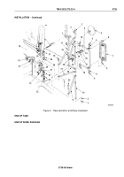
Install bracket (Figure 4, Item 26) on mounting bracket (Figure 4, Item 28) with three screws
(Figure 4, Item 27) and locknuts (Figure 4, Item 29).
2.
Install windshield wiper reservoir (Figure 4, Item 25) on bracket (Figure 4, Item 26).
3.
Install windshield wiper reservoir cap (Figure 4, Item 24) on reservoir (Figure 4, Item 25).
4.
Install hoses (Figure 4, Item 12) and (Figure 4, Item 30) on windshield wiper reservoir cap (Figure 4, Item 24)
with clamps (Figure 4, Item 22) and (Figure 4, Item 23).
5.
Insert hoses (Figure 4, Item 12) and (Figure 4, Item 30) through holes in firewall (Figure 4, Item 7).
6.
Install hoses (Figure 4, Item 17), (Figure 4, Item 30), and (Figure 4, Item 31) on tee (Figure 4, Item 16).
7.
Install jets (Figure 4, Item 15) and (Figure 4, Item 18) on cab (Figure 4, Item 32) with wing nuts
(Figure 4, Item 33) and (Figure 4, Item 19).
8.
Connect hoses (Figure 4, Item 31) and (Figure 4, Item 17) on jets (Figure 4, Item 15) and (Figure 4, Item 18).
9.
Place grommets (Figure 4, Items 20 and 21) on hoses (Figure 4, Items 12 and 30) and install on firewall
(Figure 4, Item 7).
10.
Install elbow (Figure 4, Item 8) and hose (Figure 4, Item 9) on windshield wiper control (Figure 4, Item 11).
11.
Install hose (Figure 4, Item 12) on windshield wiper control (Figure 4, Item 11) with clamp (Figure 4, Item 10).
12.
Install windshield wiper control (Figure 4, Item 11) on instrument panel (Figure 4, Item 4) with lockwasher
(Figure 4, Item 2) and nut (Figure 4, Item 1).
13.
Install knob (Figure 4, Item 14) on windshield wiper control (Figure 4, Item 11) with setscrew
(Figure 4, Item 13).
14.
Install duct hose (Figure 4, Item 5) on defrost duct (Figure 4, Item 3) with clamp (Figure 4, Item 6).
TM 9-2320-272-23-4
0737
0737-6
Back to Top


