TM-9-2320-272-23-4 - Page 1285 of 1393
REMOVAL
1.
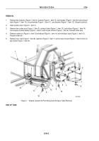
Close water manifold drain valve (Figure 1, Item 1) on right side of engine (Figure 1, Item 3).
2.
Close coolant outlet drain valve (Figure 1, Item 2) on right side of engine (Figure 1, Item 3).
NOTE
•
Have drainage container ready to catch excess coolant.
•
Use drain pans to retain leaking/draining fluids. Refer to local procedures and plans for
preventing and responding to fluid spills or leaks. Comply with local regulations when
disposing of clean up material and leaked and spilled fluids.
3.
Loosen clamp (Figure 1, Item 27) and remove hose (Figure 1, Item 20) from water manifold drain valve
(Figure
1,
Item
1).
4.
Remove nut (Figure 1, Item 10), lockwasher (Figure 1, Item 9), clamps (Figure 1, Items 12 and 24), washer
(Figure
1,
Item
22), and screw (Figure 1, Item 23) from oil dipstick tube bracket (Figure
1,
Item
8) and oil
dipstick tube (Figure 1, Item 11). Discard lockwasher.
5.
Remove screw (Figure 1, Item 18) and clamp (Figure 1, Item 19) from cab support (Figure 1, Item 13).
6.
Remove three tiedown straps (Figure 1, Item 21) from hose (Figure 1, Item 20), fuel line (Figure 1, Item 26),
and electrical harness (Figure 1, Item 25). Discard tiedown straps.
7.
Loosen clamp (Figure 1, Item 7) and remove hose (Figure 1, Item 6) from coolant outlet drain valve
(Figure
1,
Item
2).
8.
Remove screw (Figure 1, Item 16), washer (Figure 1, Item 15), and clamp (Figure 1, Item 14) from engine
access cover (Figure 1, Item 5).
9.
Remove two tiedown straps (Figure 1, Item 17) from hose (Figure 1, Item 6) and two transmission oil cooler
lines (Figure 1, Item 4). Discard tiedown straps.
TM 9-2320-272-23-4
0757
0757-2
Back to Top


