TM-9-2320-272-23-4 - Page 1293 of 1393
INSTALLATION - Continued
11.
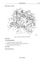
Install two tiedown straps (Figure 6, Item 17) on hose (Figure 6, Item 7) and two transmission oil cooler lines
(Figure 6, Item 5).
12.
Install hose (Figure 6, Item 7) on engine access cover (Figure 6, Item 6) with clamp (Figure 6, Item 14), washer
(Figure 6, Item 15), and screw (Figure 6, Item 16).
13.
Install hose (Figure 6, Item 7) on coolant outlet drain valve (Figure 6, Item 3) and tighten clamp
(Figure
6,
Item
8).
14.
Install three tiedown straps (Figure 6, Item 22) on hose (Figure 6, Item 21), fuel line (Figure 6, Item 27), and
electrical harness (Figure 6, Item 26).
15.
Install hose (Figure 6, Item 21) on cab support (Figure 6, Item 18), clamp (Figure 6, Item 20), and screw
(Figure
6,
Item
19).
16.
Install hose (Figure 6, Item 21) and oil dipstick tube (Figure 6, Item 13) on oil dipstick tube bracket
(Figure
6,
Item
9) with clamps (Figure 6, Item 23) and (Figure 6, Item 10), washer (Figure 6, Item 24), screw
(Figure
6,
Item
25), lockwasher (Figure 6, Item 12), and nut (Figure 6, Item 11).
17.
Install hose (Figure 6, Item 21) on water manifold drain valve (Figure 6, Item 2) and tighten clamp
(Figure
6,
Item
1).
18.
Open coolant outlet drain valve (Figure 6, Item 2) on right side of engine (Figure 6, Item 4).
19.
Open water manifold drain valve (Figure 6, Item 3) on right side of engine (Figure 6, Item 4).
TM 9-2320-272-23-4
0757
0757-10
Back to Top


