TM-9-2320-272-23-4 - Page 1282 of 1393
INSTALLATION
1.
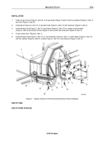
Install oil pan shroud (Figure 2, Item 6) on oil pan studs (Figure 2, Item 5) with four washers (Figure 2, Item 7)
and nuts (Figure 2, Item 8).
2.
Install elbow (Figure 2, Item 14) on exhaust tube (Figure 2, Item 13) with cotter pin (Figure 2, Item 3).
3.
Install exhaust tube (Figure 2, Item 13) and elbow (Figure 2, Item 14) on engine coolant heater
(Figure 2, Item 2) and oil pan shroud (Figure 2, Item 6) with two cotter pins (Figure 2, Item 3).
4.
Close toolbox door (Figure 2, Item 1).
5.
Install exhaust tube (Figure 2, Item 13) on crossmember (Figure 2, Item 11) and bracket (Figure 2, Item 12)
with two clamps (Figure 2, Item 9), screws (Figure 2, Item 10), and locknuts (Figure 2, Item 4).
M10013DAA
14
13
10
9
12
4
11
3
2
1
10
9
3
8
7
6
5
4
Figure 2.
Engine Coolant Oil Pan Shroud and Exhaust Tube Installation.
END OF TASK
END OF WORK PACKAGE
TM 9-2320-272-23-4
0756
0756-3/4 blank
Back to Top


