TM-9-2320-272-23-4 - Page 203 of 1393
FRAME REMOVAL - Continued
NOTE
Tag strut for installation.
9.
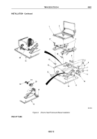
Remove two nuts (Figure 4, Item 10), lockwashers (Figure 4, Item 9), screws (Figure 4, Item 5), and lower strut
(Figure 4, Item 4) from top frame (Figure 4, Item 11). Discard lockwashers.
10.
Remove two nuts (Figure 4, Item 6), lockwashers (Figure 4, Item 7), torque rod (Figure 4, Item 8), sleeve
(Figure 4, Item 12), two springs (Figure 4, Item 2), and upper strut (Figure 4, Item 1) from top frame
(Figure
4,
Item
11). Discard lockwashers.
11.
Remove pin (Figure 4, Item 16) from crank (Figure 4, Item 14).
12.
Remove crank (Figure 4, Item 14) and washer (Figure 4, Item 13) from swivel nut (Figure 4, Item 17) on bracket
(Figure 4, Item 15).
END OF TASK
INSPECTION AND REPAIR
1.
Inspect sheet metal parts, springs, brackets, struts, and pins for breaks, bends, and cracks. Replace if broken,
bent, or cracked (TM 9-237).
2.
Inspect crank (Figure 4, Item 14), crank adjuster swivel nut (Figure 4, Item 17), torque rod (Figure 4, Item 8),
and screws (Figure 4, Item 5) for damaged threads. Replace if damaged.
3.
Inspect shock absorber (Figure 4, Item 18) for damage. Replace if damaged.
4.
Inspect adjusters (Figure 4, Item 19) and crank (Figure 4, Item 14) for breaks, bends, and cracks. Replace if
broken, bent, or cracked (TM 9-237).
TM 9-2320-272-23-4
0582
0582-8
Back to Top


