TM-9-2320-272-23-4 - Page 207 of 1393
INSTALLATION - Continued
5.
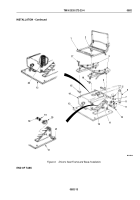
Install lower strut (Figure 6, Item 12) and upper strut (Figure 6, Item 11) on seat base (Figure 6, Item 13) with
four screws (Figure 6, Item 10), lockwashers (Figure 6, Item 9), and nuts (Figure 6, Item 8).
6.
Position spring (Figure 6, Item 22) on seat base (Figure 6, Item 13).
7.
Install two brackets (Figure 6, Item 20) on seat base (Figure 6, Item 13) with four screws (Figure 6, Item 21),
lockwashers (Figure 6, Item 19), and nuts (Figure 6, Item 18).
8.
Install shock absorber Figure 6, Item 6) on top frame (Figure 6, Item 14) with screw (Figure 6, Item 4) and nut
(Figure 6, Item 16).
9.
Install fixed end of shock absorber (Figure 6, Item 6) on seat base (Figure 6, Item 13) with screw
(Figure
6,
Item
4) and nut (Figure 6, Item 16).
10.
Install adjusters (Figure 6, Item 3) on top frame (Figure 6, Item 14) with two washers (Figure 6, Item 15), screws
(Figure 6, Item 17), four washers (Figure 6, Item 5), and locknuts (Figure 6, Item 7).
11.
Install seat frame (Figure 6, Item 1) on adjusters (Figure 6, Item 3) with four locknuts (Figure 6, Item 2).
TM 9-2320-272-23-4
0582
0582-12
Back to Top


