TM-9-2320-272-23-4 - Page 695 of 1393
INSTALLATION
NOTE
Perform Step (1) if installing new front winch.
1.
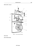
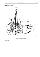
Remove four screws (Figure 2, Items 7 and 20) and washers (Figure 2, Items 6 and 19) from front winch
(Figure
2,
Item
18).
2.
Install right mounting support plate (Figure 2, Item 21) on front winch (Figure 2, Item 18) with four washers
(Figure 2, Item 19) and screws (Figure 2, Item 20).
3.
Install left mounting support plate (Figure 2, Item 5) on front winch (Figure 2, Item 18) with four washers
(Figure
2,
Item
6) and screws (Figure 2, Item 7).
4.
Position chains on front winch (Figure 2, Item 18) and attach to lifting device.
WARNING
All personnel must stand clear during lifting operations. A snapped chain, or shifting or
swinging load, may result in injury to personnel. Failure to comply may result in injury or death
to personnel.
5.
With the aid of assistant, position front winch (Figure 2, Item 18) on frame rails extensions
(Figure
2,
Items
11
and
15). Do not remove chains or lifting device until front winch is secured.
6.
Install right mounting support plate (Figure 2, Item 21) on right inner support plate (Figure 2, Item 14) with three
washers (Figure 2, Item 16), screws (Figure 2, Item 17), and locknuts (Figure 2, Item 13).
7.
Install right mounting support plate (Figure 2, Item 21) on right frame rail extension (Figure 2, Item 15) with
four washers (Figure 2, Item 22), lockwashers (Figure 2, Item 23), and screws (Figure 2, Item 1).
8.
Install left mounting support plate (Figure 2, Item 5) on left inner support plate (Figure 2, Item 10) with three
washers (Figure 2, Item 9), screws (Figure 2, Item 8), and locknuts (Figure 2, Item 12).
9.
Install left mounting support plate (Figure 2, Item 5) on left frame rail extension (Figure 2, Item 11) with four
washers (Figure 2, Item 4), lockwashers (Figure 2, Item 3), and screws (Figure 2, Item 2).
10.
Remove lifting device and chains from front winch (Figure 2, Item 18).
NOTE
Wrap all male threads with antiseize tape before installation.
11.
Connect oil supply hose (Figure 2, Item 26) to rear elbow (Figure 2, Item 27) on winch motor
(Figure
2,
Item
28).
12.
Connect oil return hose (Figure 2, Item 25) to front elbow (Figure 2, Item 24) on winch motor
(Figure
2,
Item
28).
TM 9-2320-272-23-4
0668
0668-4
Back to Top


