TM-9-2320-272-23-4 - Page 699 of 1393
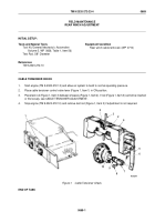
CABLE TENSIONER ADJUSTMENT
1.
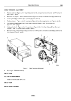
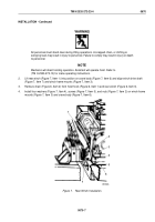
Remove cotter pin (Figure 2, Item 6), pin (Figure 2, Item 8), and pushrod yoke (Figure 2, Item 7) from pivot
arm (Figure 2, Item 5).
2.
Place test rod (Figure 2, Item 3) between sheaves (Figure 2, Item 2) on cable tensioner (Figure 2, Item 4).
3.
Loosen jamnut (Figure 2, Item 9) on pushrod (Figure 2, Item 10).
4.
Position pivot arm (Figure 2, Item 5) so sheaves (Figure 2, Item 2) are against test rod (Figure 2, Item 3).
5.
Turn pushrod yoke (Figure 2, Item 7) until holes in pushrod (Figure 2, Item 10) and pivot arm
(Figure
2,
Item
5) align.
6.
Install pushrod yoke (Figure 2, Item 7) on pivot arm (Figure 2, Item 5) with pin (Figure 2, Item 8) and pin
(Figure
2,
Item
6). Tighten jamnut (Figure 2, Item 9).
7.
Place tensioner control valve lever (Figure 2, Item 1) in OFF position and remove test rod (Figure 2, Item 3)
from sheaves (Figure 2, Item 2).
M5253DAA
1
2
3
2
4
5
6
7
8
9
10
Figure 2.
Cable Tensioner Adjustment.
8.
Stop engine (TM 9-2320-272-10).
END OF TASK
FOLLOW-ON MAINTENANCE
Install rear winch cable. (WP
0710)
END OF TASK
END OF WORK PACKAGE
TM 9-2320-272-23-4
0669
0669-2
Back to Top

