TM-9-2320-272-23-4 - Page 707 of 1393
INSTALLATION - Continued
5.
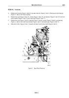
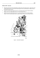
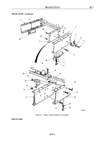
Slide winch motor (Figure 8, Item 16) backward to position at rear winch (Figure 8, Item 1), align holes in drive
coupling (Figure 8, Item 10) and winch drive shaft (Figure 8, Item 3) and install shear pin (Figure 8, Item 2)
and cotter pin (Figure 8, Item 4).
6.
Install front mounting bracket (Figure 8, Item 13) on crane body (Figure 8, Item 12) with two washers
(Figure
8,
Item
14), screws (Figure 8, Item 15), and nuts (Figure 8, Item 11).
7.
Install rear mounting bracket (Figure 8, Item 7) on crane body (Figure 8, Item 12) with two washers
(Figure
8,
Item
8), screws (Figure 8, Item 9), washers (Figure 8, Item 6), and nuts (Figure 8, Item 5).
M5263DAA
1
2
3
4
5
6
7
8
9
10
11
12
13
14
15
16
Figure 8.
Rear Winch Installation.
TM 9-2320-272-23-4
0670
0670-8
Back to Top

