TM-9-2320-272-23-4 - Page 713 of 1393
INSTALLATION
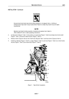
1.
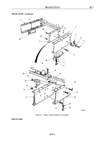
Install two channel reinforcements (Figure 2, Item 2) on frame rails (Figure 2, Item 4) with eight screws
(Figure
2, Item 12), locknuts (Figure 2, Item 11), two washers (Figure 2, Item 15) and screws
(Figure
2,
Item
16). Tighten locknuts and screws to 85 lb-ft (115 N·m).
2.
Install two end supports (Figure 2, Item 19) on channel reinforcements (Figure 2, Item 2) with four screws
(Figure 2, Item 13) and locknuts (Figure 2, Item 18). Tighten locknuts to 120 lb-ft (163
N·m).
3.
Install two end supports (Figure 2, Item 19) on crossmember (Figure 2, Item 20) with four washers
(Figure
2,
Item 10), screws (Figure 2, Item 21), and locknuts (Figure 2, Item 17). Tighten locknuts to
120
lb
-
ft
(163 N·m).
4.
Install two frame extensions (Figure 2, Item 1) on channel reinforcements (Figure 2, Item 2) with eight screws
(Figure 2, Item 6) and locknuts (Figure 2, Item 23). Tighten locknuts to 85 lb-ft (115 N·m).
5.
Install two loop tiedowns (Figure 2, Item 3) on frame extensions (Figure 2, Item 1) with four washers
(Figure
2,
Item
4), screws (Figure 2, Item 5), and locknuts (Figure 2, Item 24).
6.
Install two brackets (Figure 2, Item 22) on frame extensions (Figure 2, Item 1) with six washers
(Figure
2,
Item
7), lockwashers (Figure 2, Item 8), and screws (Figure 2, Item 9).
TM 9-2320-272-23-4
0671
0671-4
Back to Top

