TM-9-2320-272-23-4 - Page 717 of 1393
TESTING
CAUTION
Selection of grade used in this procedure should be within the tolerance capabilities of the
second vehicle. Failure to comply may result in damage to equipment.
NOTE
The procedures for testing and adjustment of front and rear winch automatic brakes are the
same. This procedure covers the front winch automatic brake. Refer to TM 9-2320-272-10
for winch operation.
1.
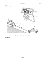
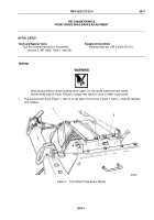
Position test vehicle (Figure 1, Item 1) at top of steep grade, facing downhill, with engine running
(TM
9-2320-272-10).
2.
Position second vehicle (Figure 1, Item 4) at bottom of steep grade, facing uphill, with engine running. Refer
to operator's manual for second vehicle.
WARNING
•
Never stand between vehicles during test. Assistant must remain in second vehicle to
engage service brakes if cable snaps or winch automatic brake fails while towing vehicle.
Failure to comply may result in injury or death to personnel.
•
Wear hand protection when handling winch cable. Broken wires may be sharp. Failure
to comply may result in injury or death to personnel.
•
A minimum of four turns of cable must remain on winch drum at all times. Failure to comply
may result in damage to equipment, injury, or death to personnel.
3.
Release winch cable (Figure 1, Item 3) (TM 9-2320-272-10) from test vehicle (Figure 1, Item 1) and rig to
second vehicle (Figure 1, Item 4).
4.
Refer to Operator's Manual for second vehicle (Figure 1, Item 4) and prepare vehicle (Figure 1, Item 1)
as
follows:
a.
Place transmission lever (Figure 1, Item 5) in NEUTRAL position.
b.
Disengage parking brake (TM 9-2320-272-10).
c.
Disengage front wheel drive lever if engaged (TM 9-2320-272-10).
5.
Prepare front winch (Figure 1, Item 2) of vehicle (Figure 1, Item 1) for winding (TM 9-2320-272-10).
6.
Pull back winch control lever (Figure 1, Item 6) to WIND position, pull second vehicle (Figure 1, Item 4) part
way up grade, and observe movement of second vehicle.
a.
If second vehicle (Figure 1, Item 4) rolls backward, go to ADJUSTMENT and adjust automatic winch
brake of vehicle (Figure 1, Item 1).
b.
If second vehicle (Figure 1, Item 4) holds steady on the incline, no adjustment is required.
7.
Push winch control lever (Figure 1, Item 6) forward to WINCH position and unwind winch cable
(Figure
1,
Item
3) until second vehicle (Figure 1, Item 4) is on level ground.
8.
Remove winch cable (Figure 1, Item 3) from second vehicle (Figure 1, Item 4) if no adjustment is required.
TM 9-2320-272-23-4
0672
0672-2
Back to Top

