TM-9-2320-272-23-4 - Page 793 of 1393
INSTALLATION
1.
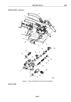
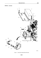
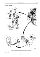
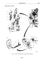
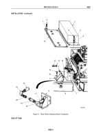
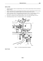
Align holes in rear coupling hub (Figure 3, Item 20) and driveshaft (Figure 3, Item 21) and install coupling
(Figure 3, Item 19) on winch driveshaft with shear pin (Figure 3, Item 23) and cotter pin (Figure 3, Item 22).
NOTE
Wrap all male pipe threads with antiseize tape before installation.
2.
Install rear bracket (Figure 3, Item 28) on winch motor (Figure 3, Item 8) with six lockwashers
(Figure
3,
Item
15) and screws (Figure 3, Item 16). Tighten screws 60 to 70 lb-ft (81
to
95
N·m).
NOTE
Assistant will help with Step (3).
3.
Place key (Figure 3, Item 13) in slot of winch motor shaft (Figure 3, Item 12) and install winch motor
(Figure
3, Item 8) on coupling (Figure 3, Item 19). Ensure key is visible in setscrew hole (Figure 3, Item 17).
4.
Install rear bracket (Figure 3, Item 28) on frame crossmember (Figure 3, Item 24) with four washers
(Figure
3,
Item 26), two screws (Figure 3, Item 25), and two locknuts (Figure 3, Item 27). Tighten locknuts
60
to
70
lb-ft (81 to 95 N·m).
5.
Install pipe nipple (Figure 3, Item 6), elbow (Figure 3, Item 7), valve (Figure 3, Item 29), adapter
(Figure
3,
Item
30), and tee (Figure 3, Item 33) on winch motor (Figure 3, Item 8).
6.
Connect two hose connectors (Figure 3, Items 31 and 32) to tee (Figure 3, Item 33).
7.
Apply sealing compound to threads of setscrew (Figure 3, Item 14) and install in hole (Figure 3, Item 17) in
front coupling hub (Figure 3, Item 18).
8.
Install elbow (Figure 3, Item 10) on winch motor (Figure 3, Item 8) with o-ring (Figure 3, Item 9).
9.
Connect hydraulic hose (Figure 3, Item 11) on elbow (Figure 3, Item 10).
10.
Connect three hydraulic hoses (Figure 3, Item 1) to winch motor (Figure 3, Item 8) with o-rings
(Figure
3,
Item
5), six clamps (Figure 3, Item 4), 12 washers (Figure 3, Item 3), and screws
(Figure
3,
Item
2).
11.
Install pipe nipple (Figure 3, Item 21) and elbow (Figure 3, Item 22) on winch motor (Figure 3, Item 18) with
elbow pointed up.
TM 9-2320-272-23-4
0682
0682-6
Back to Top

