TM-9-2320-272-23-4 - Page 783 of 1393
REMOVAL
CAUTION
Plug hydraulic hoses to prevent dirt from entering.
NOTE
All hoses and fittings must be tagged for installation.
1.
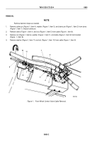
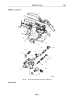
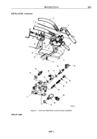
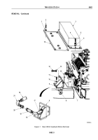
Disconnect hoses (Figure 1, Items 1, 4, 5, and 6) from control valve (Figure 1, Item 7). Tag for installation.
2.
Remove cotter pin (Figure 1, Item 14), washer (Figure 1, Item 15), and clevis pin (Figure 1, Item 3) from cable
clevis (Figure 1, Item 2). Discard cotter pin.
3.
Remove three locknuts (Figure 1, Item 13), screws (Figure 1, Item 10), and control valve (Figure 1, Item 7)
from bracket (Figure 1, Item 12). Discard locknuts.
4.
Remove four locknuts (Figure 1, Item 8), screws (Figure 1, Item 11), and bracket (Figure 1, Item 12) from frame
(Figure 1, Item 9). Discard locknuts.
5.
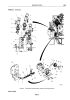
Remove elbow (Figure 1, Item 20) and adapter (Figure 1, Item 25) from fitting (Figure 1, Item 19) and elbow
(Figure 1, Item 26).
6.
Remove fittings (Figure 1, Items 16 and 19) and elbows (Figure 1, Items 18 and 26) from control valve
(Figure
1, Item 7).
7.
Remove four o-rings (Figure 1, Item 17) from fittings (Figure 1, Items 16 and 19) and elbows
(Figure 1, Items 18 and 26). Discard o-rings.
8.
Remove plug (Figure 1, Item 21), spring (Figure 1, Item 23), and relief valve (Figure 1, Item 24) from control
valve (Figure 1, Item 7).
9.
Remove o-ring (Figure 1, Item 22) from plug (Figure 1, Item 21). Discard o-ring.
TM 9-2320-272-23-4
0681
0681-2
Back to Top

