TM-9-2320-272-23-4 - Page 778 of 1393
REMOVAL - Continued
5.
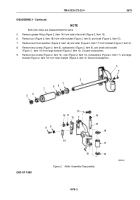
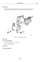
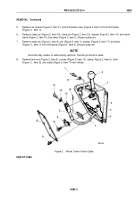
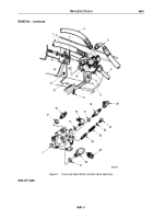
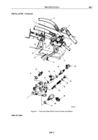
Remove six screws (Figure 2, Item 11) and shift panel cover (Figure 2, Item 12) from shift panel
(Figure
2,
Item
3).
6.
Remove cotter pin (Figure 2, Item 16), clevis pin (Figure 2, Item 13), washer (Figure 2, Item 14), and cable
clevis (Figure 2, Item 15) from lever (Figure 2, Item 2). Discard cotter pin.
7.
Remove cotter pin (Figure 2, Item 4), pin (Figure 2, Item 1), washer (Figure 2, Item 17), and lever
(Figure
2,
Item
2) from shift panel (Figure 2, Item 3). Discard cotter pin.
NOTE
Grommet may remain on cable during removal. Transfer grommet to cable.
8.
Remove two nuts (Figure 2, Item 5), screws (Figure 2, Item 10), clamp (Figure 2, Item 9), shim
(Figure
2,
Item
8), and cable (Figure 2, Item 7) from vehicle.
M6022DAA
11
12
10
9
8
13
14
15
16
17
1
2
3
4
5
6
7
Figure 2.
Winch Control Valve Cable.
END OF TASK
TM 9-2320-272-23-4
0680
0680-3
Back to Top

