TM-9-2320-272-23-4 - Page 780 of 1393
INSTALLATION - Continued
NOTE
Place shift lever in NEUTRAL position.
5.
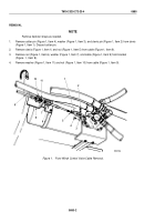
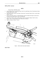
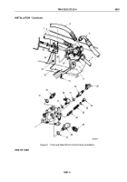
Install nut (Figure 4, Item 11) and washer (Figure 4, Item 12) on cable (Figure 4, Item 10) and feed end of cable
through bracket (Figure 4, Item 9).
6.
Install washer (Figure 4, Item 8), nuts (Figure 4, Items 6 and 7), and clevis (Figure 4, Item 1) on end of cable
(Figure 4, Item 10).
7.
Position clevis (Figure 4, Item 1) on valve shaft (Figure 4, Item 3) and adjust nuts (Figure 4, Items 6 and 7)
until holes in end of cable (Figure 4, Item 10) and shaft align.
8.
Install clevis pin (Figure 4, Item 2), washer (Figure 4, Item 4), and cotter pin (Figure 4, Item 5) in clevis
(Figure
4,
Item
1) and shaft (Figure 4, Item 3). Bend ends of cotter pin.
9.
Tighten nuts (Figure 4, Items 6, 7, and 9).
M6024DAA
4
3
5
6
7
8
9
10
11
12
1
2
Figure 4.
Winch Control Valve Cable Installation.
END OF TASK
TM 9-2320-272-23-4
0680
0680-5
Back to Top

