TM-9-2320-272-23-4 - Page 795 of 1393
INSTALLATION - Continued
12.
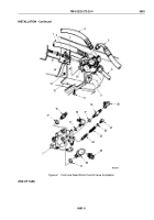
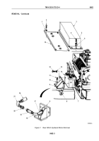
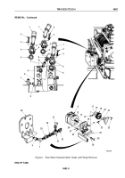
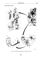
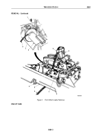
Install front bracket (Figure 4, Item 9) on winch motor (Figure 4, Item 14) with three lockwashers
(Figure
4,
Item
13) and screws (Figure 4, Item 12). Tighten screws 60 to 70 lb-ft (81
to
95
N·m). Turn elbow
(Figure 4, Item 18) to point left.
13.
Install valve (Figure 4, Item 19), adapter (Figure 4, Item 20), and elbow (Figure 4, Item 21) on elbow
(Figure
4, Item 18).
14.
Connect hose connector (Figure 4, Item 16) to elbow (Figure 4, Item 21).
15.
Install front bracket (Figure 4, Item 9) on frame (Figure 4, Item 7) with two washers (Figure 4, Item 10), screws
(Figure 4, Item 11), and locknuts (Figure 4, Item 8). Tighten locknuts 60 to 70 lb-ft (81
to
95
N·m).
16.
Install floor plate (Figure 4, Item 15) on frame (Figure 4, Item 7) with four washers (Figure 4, Item 1) and screws
(Figure 4, Item 2). Tighten screws 60 to 70 lb-ft (81 to 95 N·m).
17.
Install cover (Figure 4, Item 3) on frame (Figure 4, Item 7) with five washers (Figure 4, Item 6), lockwashers
(Figure 4, Item 5), and screws (Figure 4, Item 4). Tighten screws 60 to 70 lb-ft (81 to 95 N·m).
TM 9-2320-272-23-4
0682
0682-8
Back to Top

