TM-9-2320-272-23-5 - Page 139 of 623
INSTALLATION
1.
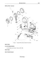
Install bracket tube (Figure 2, Item 16) on bracket (Figure 2, Item 9) with two U-bolts (Figure 2, Item 15), four
washers (Figure 2, Item 8), and locknuts (Figure 2, Item 7).
NOTE
Perform Step (2) for vehicles equipped with machine gun mount kit.
2.
Install bracket (Figure 2, Item 19) on bracket post (Figure 2, Item 23) with screw (Figure 2, Item 3), washer
(Figure 2, Item 4), locknut (Figure 2, Item 5), U-bolt (Figure 2, Item 6), two washers (Figure 2, Item 17), and
locknuts (Figure 2, Item 18)
3.
Install bracket (Figure 2, Item 19) on bracket tube (Figure 2, Item 16) with screw (Figure 2, Item 3), washer
(Figure 2, Item 4), locknut (Figure 2, Item 5), U-bolt (Figure 2, Item 6), two washers (Figure 2, Item 17), and
locknuts (Figure 2, Item 18).
4.
Install support tube (Figure 2, Item 2) on bracket tube (Figure 2, Item 16) and bracket (Figure 2, Item 19) with
pin (Figure 2, Item 21) and wing screw (Figure 2, Item 20).
5.
Insert cable (Figure 2, Item 22) and mounting plate (Figure 2, Item 1) on support tube (Figure 2, Item 2).
6.
Install washer (Figure 2, Item 11), clamp (Figure 2, Item 10) with cable (Figure 2, Item 22), and screw-
assembled lockwasher (Figure 2, Item 12) on bracket (Figure 2, Item 9).
7.
Connect two leads (Figure 2, Item 13) to connectors (Figure 2, Item 14).
TM 9-2320-272-23-5
0781
0781-4
Back to Top


